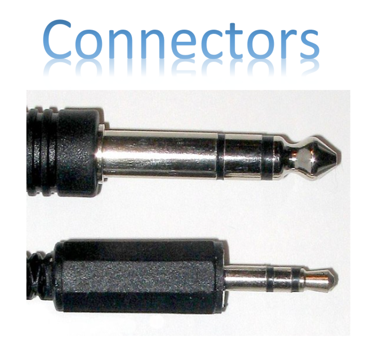
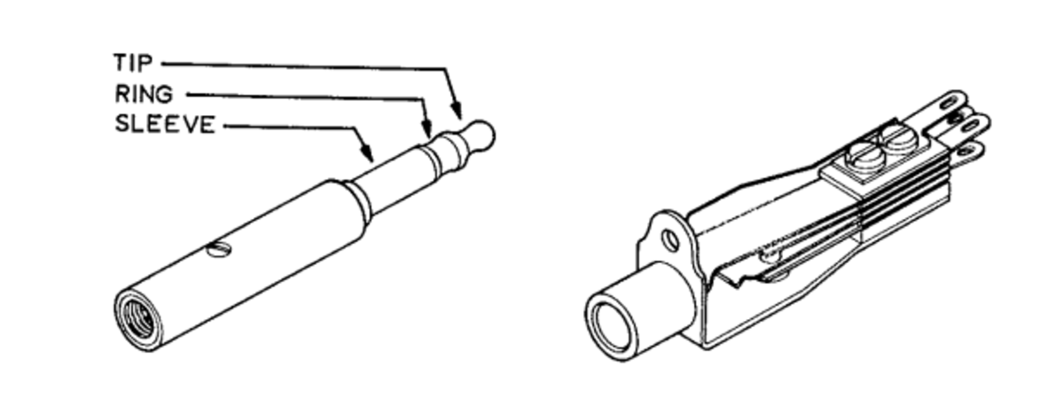
Post Office Jack
Originally used by the British Post Office (PO), these 1/4" Jack lookalikes were once widely used in the broadcast industry. In spite of their similar appearance, PO316 jacks or B-gauge jacks, as they are known, are not compatible with 1/4" mono and stereo jacks due to the smaller tip. The PO316 jack was once the most common audio connector. It has three contacts, the tip, ring and sleeve, which provided the connections for a balanced audio circuit with a screen. Rows of jack, often 20 in number, are called jackfields. Circuits involving bay mounted equipment appear on jacks and are connected together with what was called “double enders”. These are cables, ranging from 30cm to 3 metres long, with a PO316 plug on each end. Double enders are available with several sheath colours. At the BBC, those that had blue sheaths had the sleeve circuit connected to a screen. Red, black and green cords were unscreened and the sleeve circuit is made with a third conductor in the cable. Yellow cords were “phase reversed”, where the tip and ring circuits were crossed-over, so reversed the polarity of a balanced circuit. There is more on jackfields later in this article.
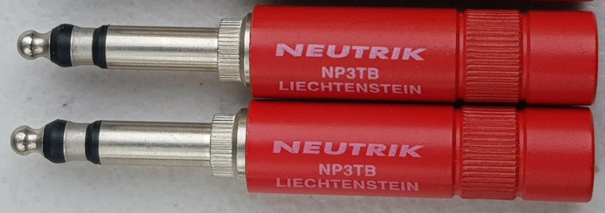
Bantam Jacks
Bantam jacks are a smaller version of the PO jack described above. They were typically used when space was restricted.
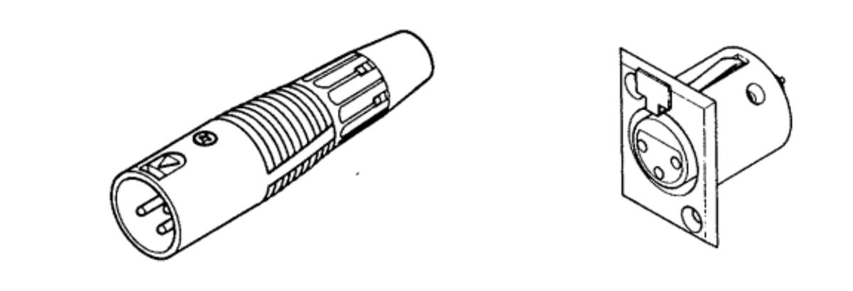
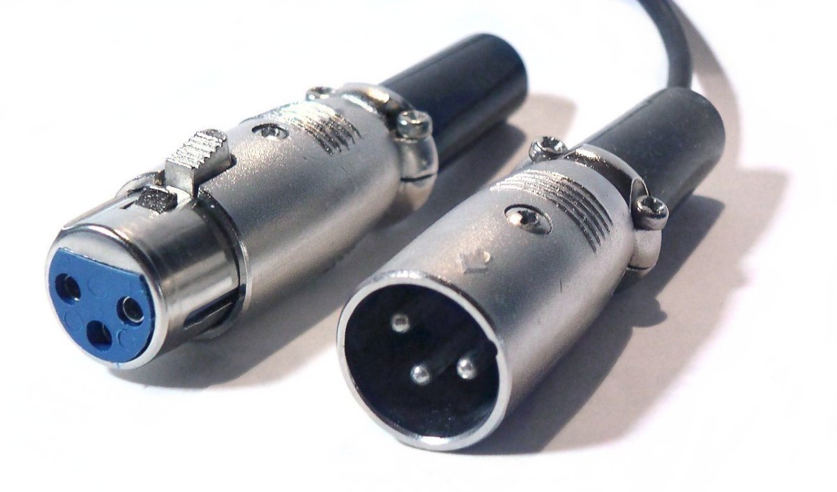
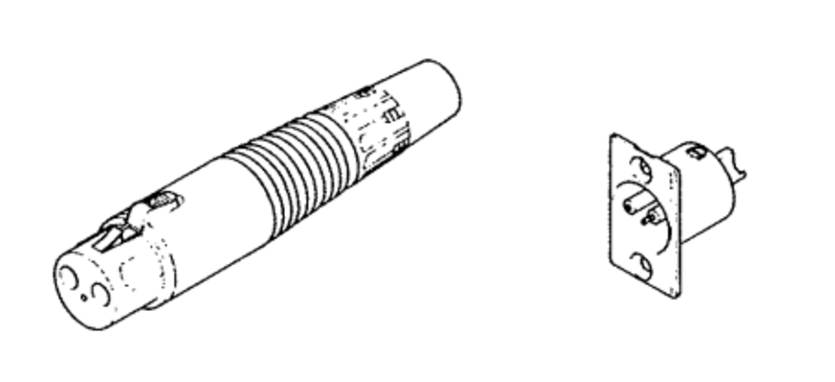
XLR
The XLR connectors can be either in-line or panel mounted. They are liked because they are rugged and lock into position, so that they aren’t accidentally removed. The 3-pin version is normally used for audio circuits, where Pin 1 is ground (X), Pin 2 is the (L)ine and Pin 3 is (R)eturn for a balanced circuit. XLRs can be obtained with multiple pins, but these are generally not used for audio.
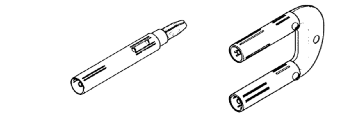
MUSA
The MUSA connector is the video equivalent of the Post Office jack. It is a type of co-axial connector and is used on video jackfields and is available in the in-line version or as a U-shaped double plug to connect two adjacent circuits on a video jackfield. MUSA stands for Multiple Unit Steerable Antenna and it was developed by the British Post Office.
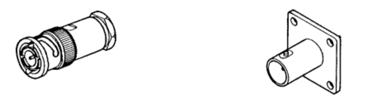
BNC
The BNC connector is found on lots of equipment. It has a locking action due to the bayonet design. There are two versions of BNC: One is 75Ω and used for video equipment, the other is 50Ω and is used for audio. Both connectors are physically the same and can be interchanged but the impedance may not be matched. BNC stands for Bayonet Neill-Concelman after its bayonet locking mechanism and its two inventors, Paul Neill and Carl Concelman.
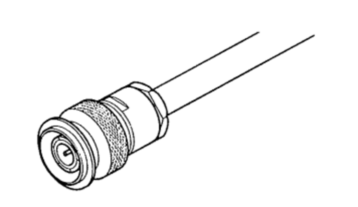
TNC
The TNC connector is essentially a screw version of the BNC connector that was mentioned above. The connector has a 50Ω impedance, similar to the audio version of the BNC, and is predominantly used for higher frequencies, as it has better performance than the BNC at higher frequencies. TNC stands for Threaded Neill-Concelman because it is a threaded connector and after its two inventors, Paul Neill and Carl Concelman.
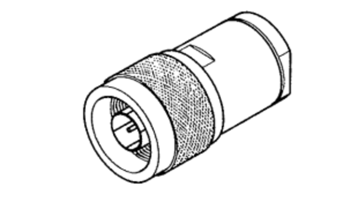
N-Type
This is a larger version of the TNC connector and is able to handle considerably higher powers. It is common on commercial RF test equipment and was used by the BBC on their own equipment designs. Like the BNC, there is a 50Ω version and a 75Ω version. The 75Ω is primarily used in television systems, with the 50Ω version for audio systems. The two connectors are not compatible and connecting a 50Ω version with a 75Ω connector (and vice versa) can lead to damaging the connectors. The connector is called N-type after its inventor, Paul Neill.
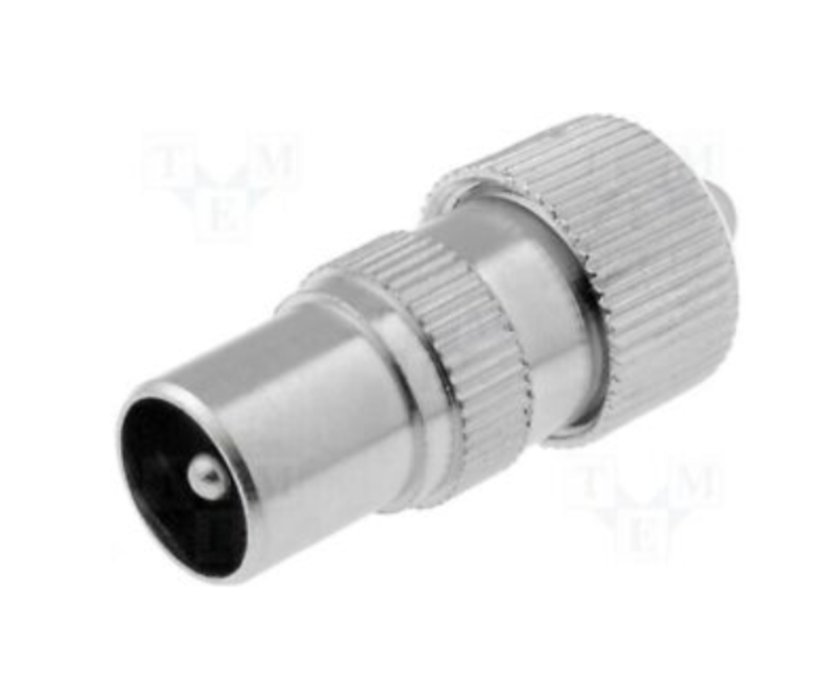
Belling Lee
The Belling Lee connector is used for co-axial cable and can commonly be found as the RF input on domestic televisions. The TV aerial connector was originally invented by the Belling & Lee Company in the United Kingdom at the time of the first BBC television broadcasts in the early 1920s.
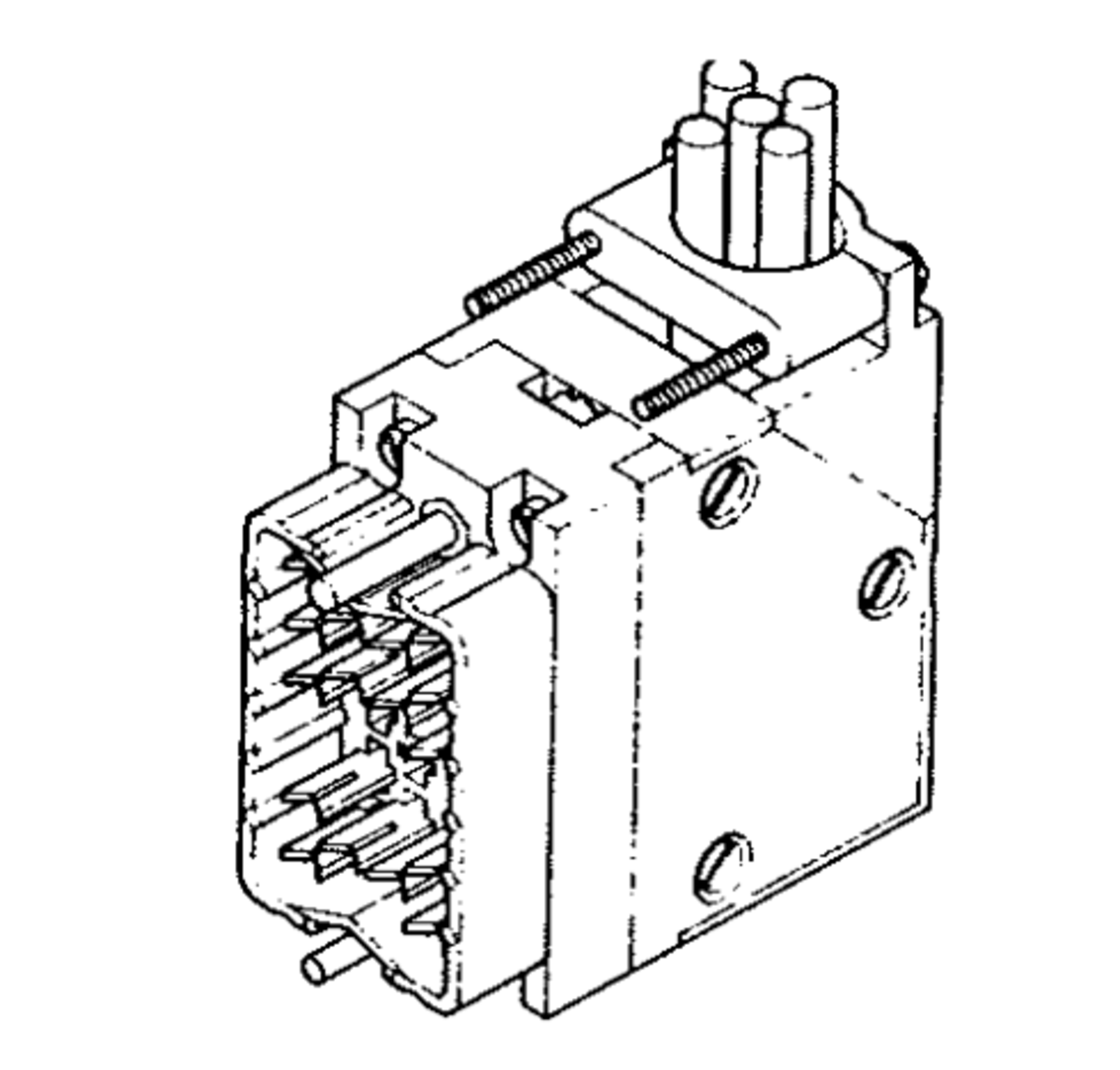
Hypertac
The Hypertac was a multipole connector that was used to connect reel-to-reel tape machines and gramaphone (turntable) decks in studio installations. The Hypertac connector could handle all the programme and the remote control connections required, as it could have up to 50 pins.
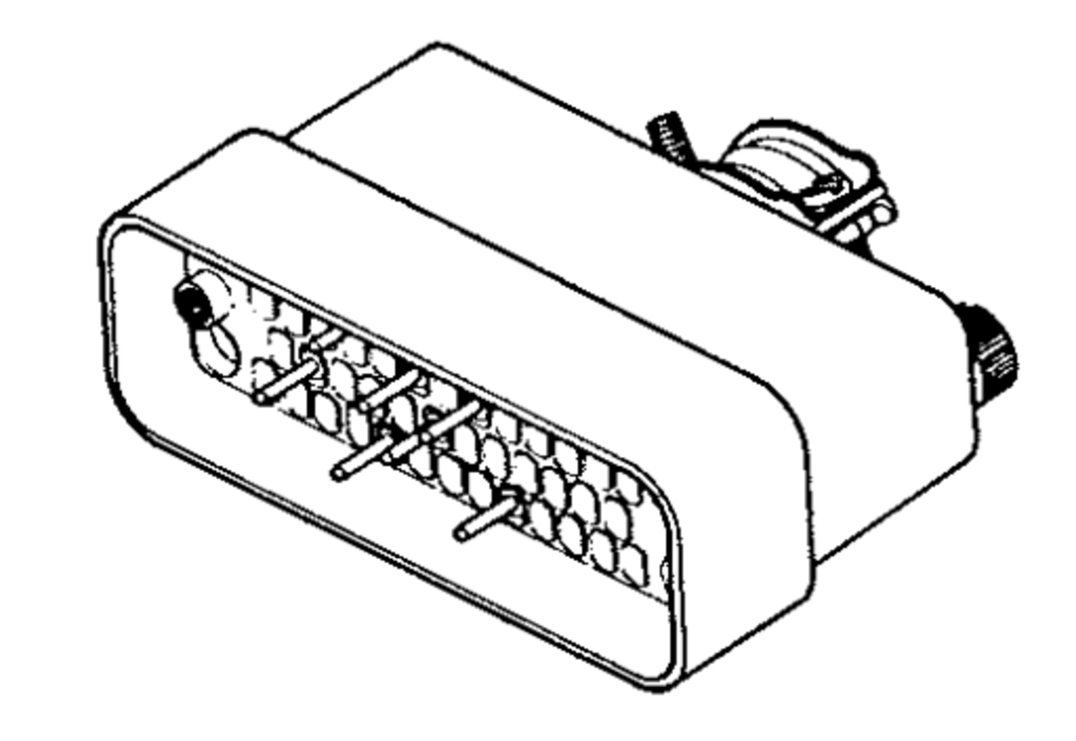
Varicon
The Varicon connector was available in 20, 38, 56 and 120 pin versions. It was widely used for connecting audio and other low frequency signals in semi-permanent installations. The connector is compact and the gold-plated contacts are the same in both the plug and the socket. The Varicon connectors were used from the late 1980s as they facilitated more audio, and control signals than the Hypertac connectors that they replaced. Typically, a reel-to-reel tape machine would have its audio input and output provided using these connectors along with play/pause/record and fast-forward/rewind remote controls along with the status lights.
D-Type
These connectors are common on digital equipment and are available in 9, 15, 25, 37 and 50 way versions. The connectors were used in broadcasting for remotes and indicators but, in some cases, for audio connections.
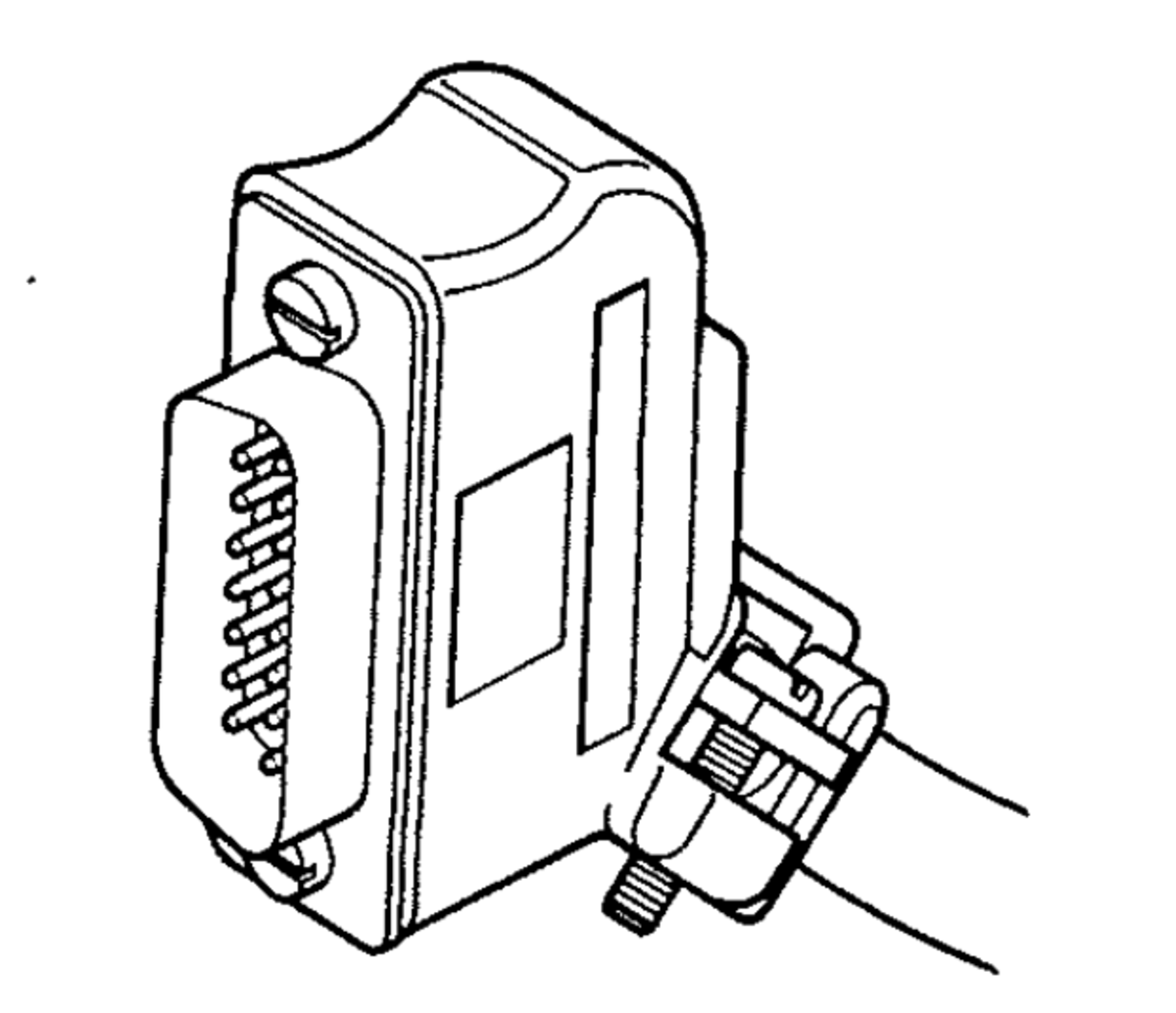
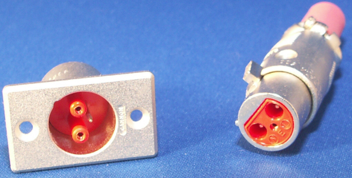
XLR LNE
This connector is similar in size to the XLR audio connector but they were used for connecting the main power to equipment. They are normally fitted with a red plastic moulding and strain relief sleeve to distinguish it from other XLRs. The XLR LNE connector has a different pin arrangement, so it cannot be accidentally mated with other XLR connectors. Like other XLR connectors, these were locking connectors. Oddly, the plug was used to supply power on pins shrouded by small holes to stop fingers from coming into contact with the pins. They were not extensively used and stopped being installed after there were concerns about their safety, and the industry moved onto IEC connectors.
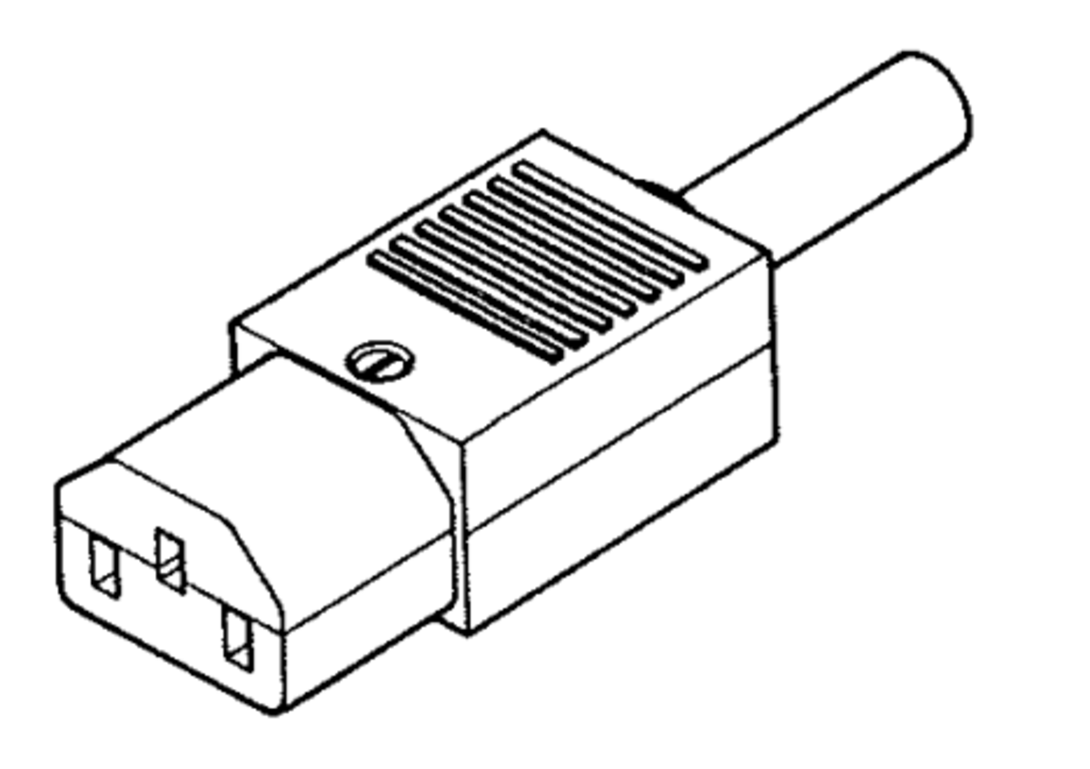
IEC C13
The IEC C13 mains connector is a non-locking connector used to supply mains voltage to equipment. It is commonly referred to as just an IEC or sometimes called a kettle plug. These are now very common on appliances and pretty much the industry standard for mains connectors. IEC stands for International Electrotechnical Commission.
PO Jackfields
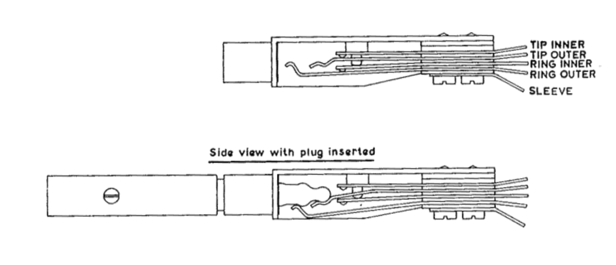
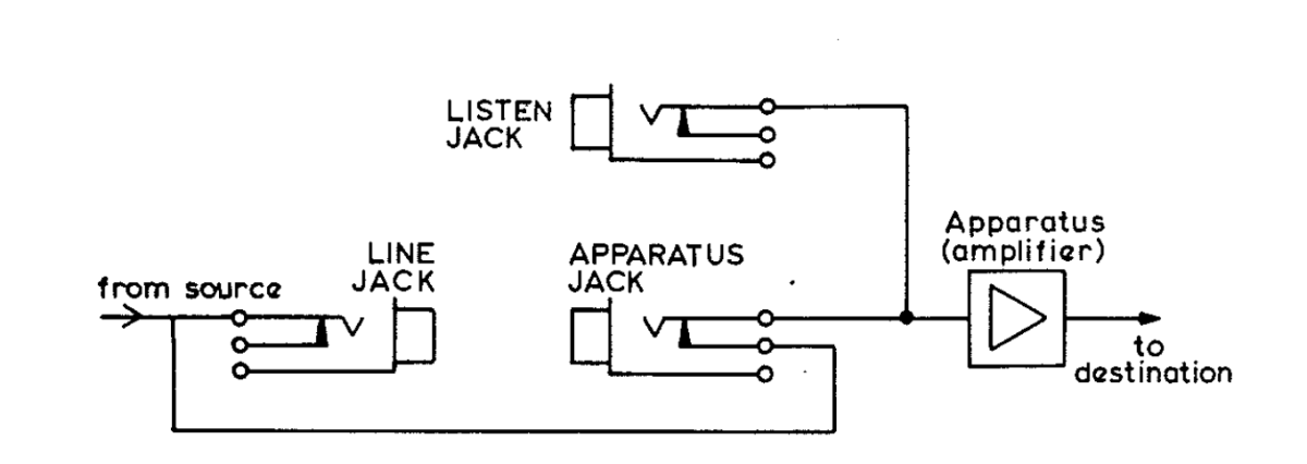
Audio Jackfields using PO316 jacks were widely used by the BBC to patch audio signals within studios and also in Control Rooms, to route audio from one area to another. The arrangement of Jacks on a jackfield was generally to have listen jacks above break jacks. Plugging headphones into the listen jack allowed you to confirm the output of an outside source, a studio, or an item of equipment. Using a double ender, the listen jack could be overplugged to any destination. This functionality relies on the configuration of a PO Socket, which is shown below: With no plug in the jack, the outers are connected to their respective inners. When a plug is inserted, it makes contact with the outers and disconnects the inners. This allows predetermined programme distribution without the use of patch cords. Double enders can then be used to overplug the “normal” circuits. A common arrangement of three jacks as part of a programme chain is shown above. The apparatus jack can be used to “break” the original signal away from the destination by overplugging with a different source. The original source can be routed from the line jack into another amplifier. The apparatus jack is usually labelled in RED to indicate that it breaks the signal path.
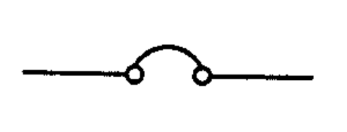
Audio Jack Symbols
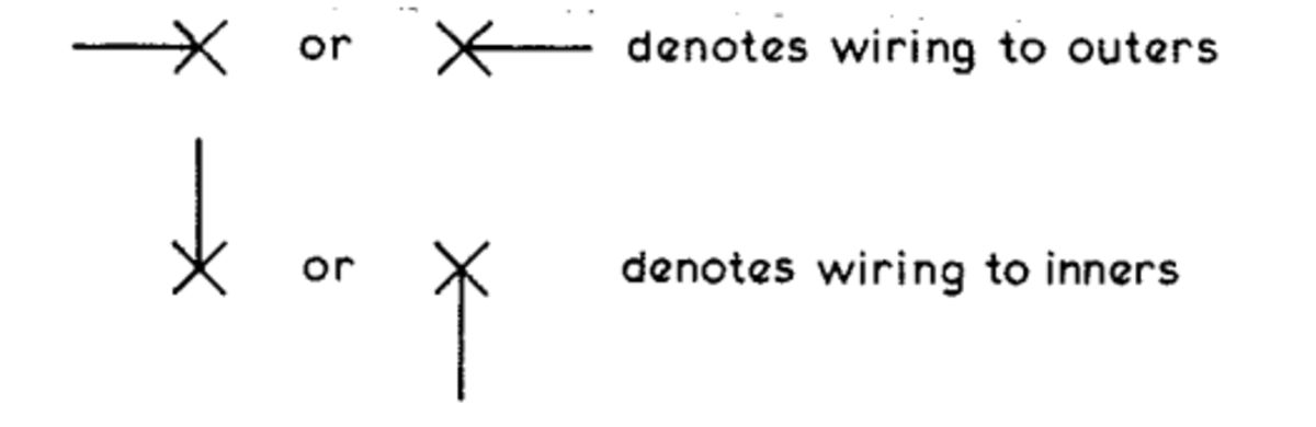
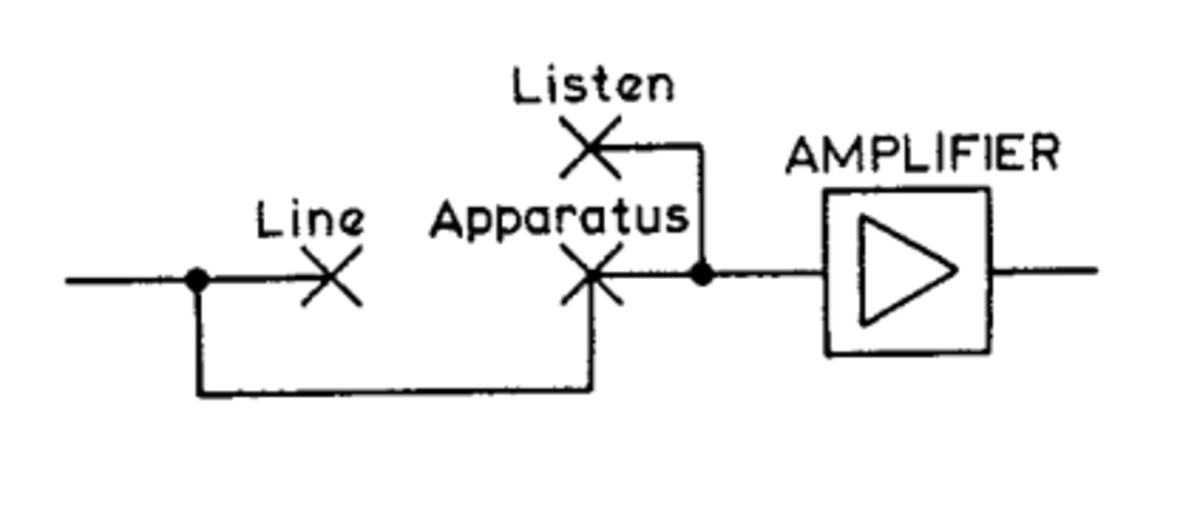
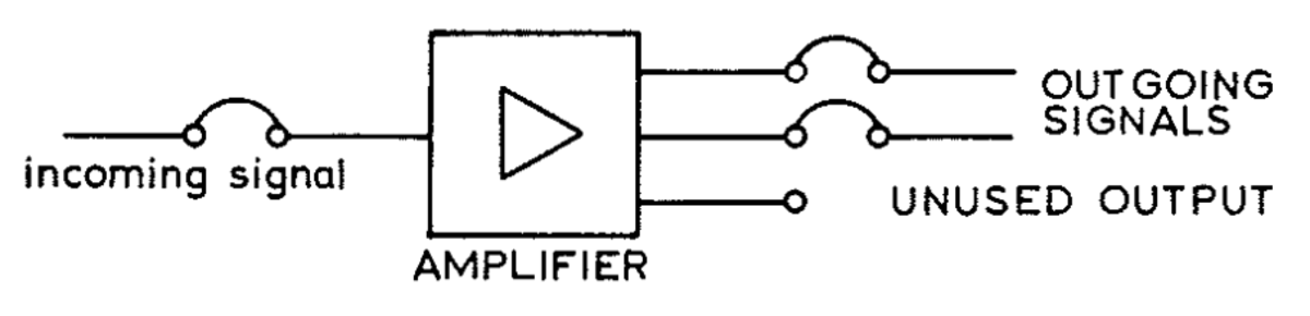
The symbols used above are not convenient to draw and, on large diagrams, make it appear cluttered. A simplified jack symbol is often used: The diagram above can thus be drawn as:
Video Jackfields
Two rows of MUSA sockets are mounted on a single panel. Sources of video and outputs from distribution amplifiers are connected to the upper row. Destinations and inputs to equipment are normally connected to the lower row. By using MUSA U-link connectors, the predetermined signal routing can be achieved in a convenient manner. If an unusual arrangement is required, the U-links can be removed and connection made with MUSA double enders. A typical video jack symbol is shown below: The above symbol represents a MUSA U-link connection. The curved part representing the removeable plug. A video distribution would be represented by the diagram below:
Audio Wiring Colour Code
We have already seen that balanced audio circuits require two conductors in addition to a screen. It is important that the order of the conductors is maintained throughout the programme chain. To simplify the identification of conductors in a cable system, colour coding is used. Each pair consists of a primary and a secondary conductor. Primary colours are as follows:
Blue B Orange O Green G Brown Br Slate S
Secondary colours are as follows:
White W Red R Black Bk Yellow Y Violet V
The first five pairs in a cable take each primary colour in turn with white, the first secondary colour. Pairs 6 to 10 take the primary colours with red, and so on. Thus the sequence is: Blue/White, Orange/White, Green/White, Brown/White, Slate/WhiteBlue/Red, Orange/Red, Green/Red, Brown/Red, Slate/RedBlue/Black, Orange/Black, etc When wiring to a PO Jack, the primary colour connects to the tip and the secondary colour to the ring. For an XLR, the primary goes to pin 2 (Line) and the secondary pin 3 (Return). Pin 1 is the screen. This content is accurate and true to the best of the author’s knowledge and is not meant to substitute for formal and individualized advice from a qualified professional. © 2022 Mr Singh