This article serves as a first hand application reference for implementing reliable protection on medium-voltage distribution transformers (11 kV - 33 kV) through commonly available microprocessor MV relays (Siemens, Schneider and GE). The protection philosophy incorporates three broad steps:
Protection Functions Required for MV Transformers
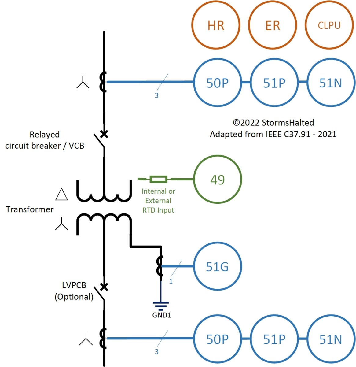
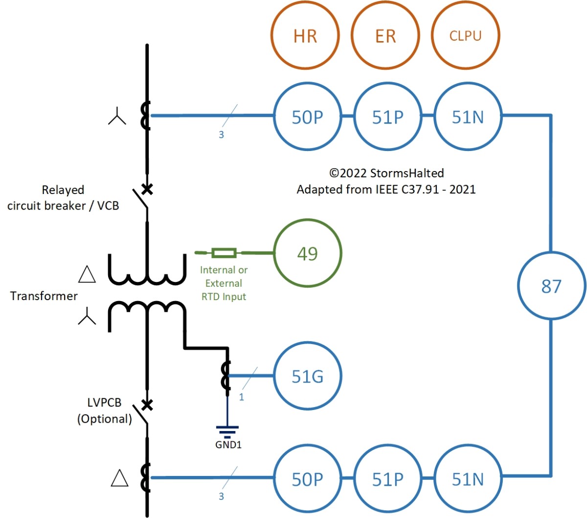
The eight essential protection functions required for transformer protection are listed in the table below. The 50G/P and 51G/P functions are required on both the HV and LV sides. The LV side protection may utilize a low voltage power circuit breaker (LVPCB) instead of a relay, that may be fed from secondary side CTs. Protection schematics demonstrate these essential protection functions. The 87 - differential protection is conveniently not used for transformers rated less then 10 MVA to reduce system costs and avoid adding extra complexity.
Plotting the Time-Current Curve (TCC)
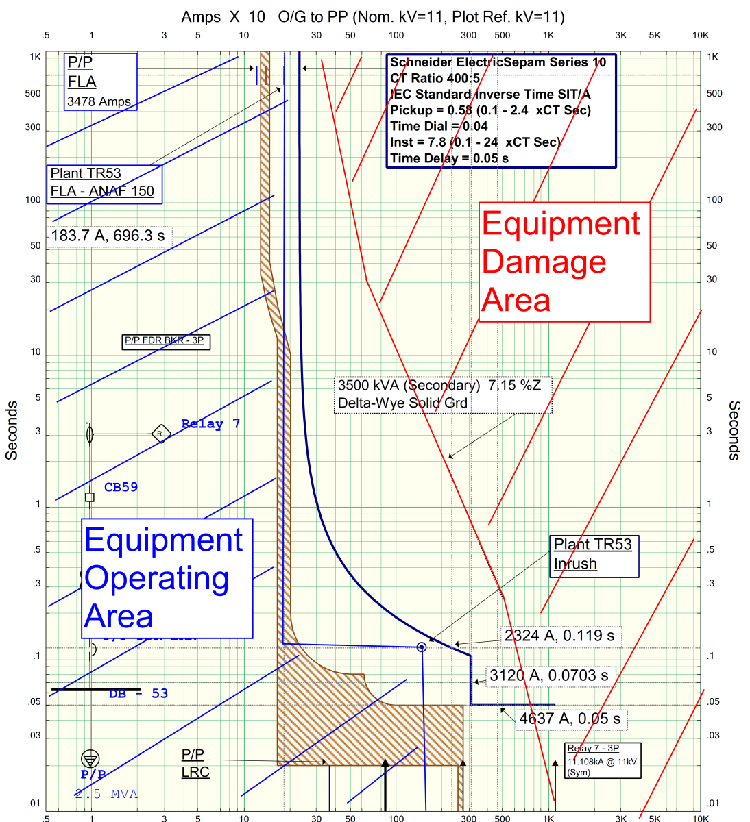
To begin applying the aforementioned protection functions on a typical transformer, we first need to plot the TCC curve. To begin plotting the TCC curve of the transformer, understanding of the following cornerstones is required. Copyrights © 2022 Ali Khan (Author) Copyrights © 2022 Ali Khan (Author) Next, a calculation of the above three is required. Transformer Inrush Current: The magnetizing inrush current a transformer draws when it is energized. Transformer Damage Curve: The thermal and mechanical limit of operation of the transformer. Beyond this limit the transformer suffers permanent damage. A transformer’s operating zone is to defined thereafter. Transformer Inrush Current: This is usually taken as 8 or 12 times the FLA and is plotted at 0.12 seconds (06 AC cycles) on the TCC plot. e.g for a transformer rated 3.5 MVA @ 11 kV pri, Inrush = 8 x 183 = 1,464 Amps. Transformer Damage Curve: Plotted according to the standard guidelines of IEEE C57.109-1993 for liquid-immersed transformers and IEEE C57.12.59-2001 for dry-type transformers.
Right side of the transformer damage curve is the equipment damage area. Left side of the FLA and Inrush Point is the equipment operating area. The TCC is placed in between these two areas as follows.
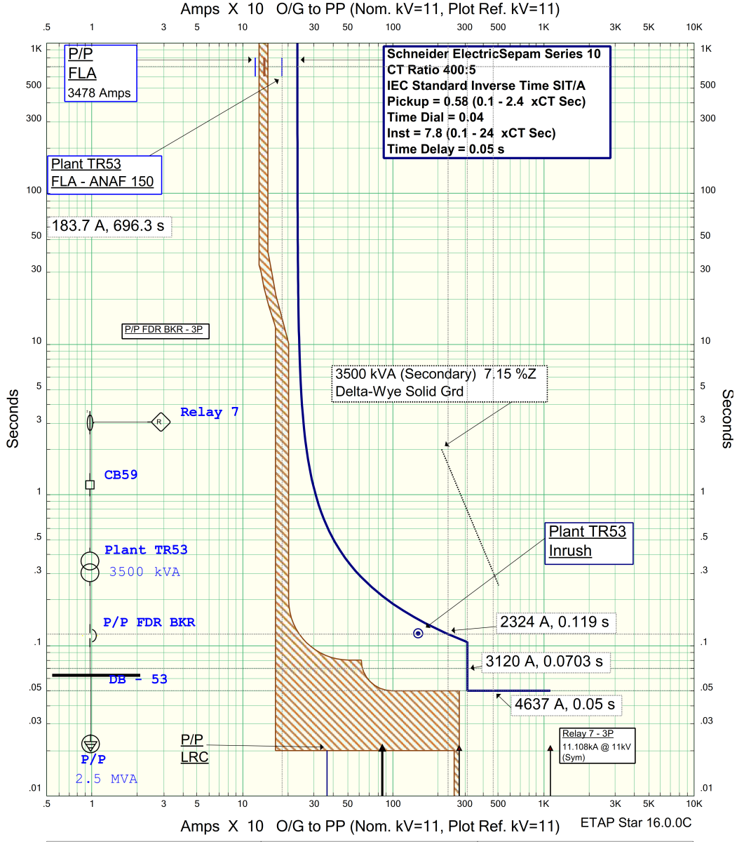
The actual TCC curve is then placed in between the operating and damage areas, above the FLA and inrush points and below the transformer damage curve. The exact position and characteristic of the curve depends on coordination with other upstream and downstream devices which is beyond the scope of this article.
Configuring Relays for Transformer Protection
Once you know the protection functions and have plotted the TCC curve, this curve now needs to be programmed into the microprocessor relay for the protection functions to work as desired. Microprocessor relays require certain parameters to be fed into their registers via proprietary software that are unique to the manufacturer of the relay, so that they can accurately mimic the plotted TCC curves. From our assessment of common relays offered by market leading manufactures, such as:
Siemens Siprotec® 7SJ602 series Schneider Electric’s Sepam® series GE Multilin® series
We have picked out the parameters that you should know, along with their calculation guidelines, in order to precisely mimic the TCC plot of your choice into the relay.
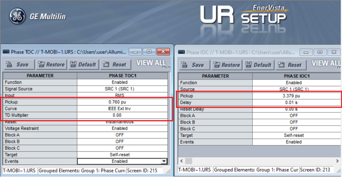
Relay Parameters for 50P/51P - Instantaneous and Time Overcurrent Function
We will now show you how you can mimic our example TCC curve shown above in a microprocessor relay.
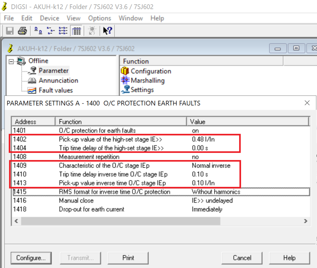
Relay Parameters for 50G/51G - Instantaneous and Time Ground Overcurrent Function
The required parameters for 50G/51G functions follow the same recommendations as 50P/51P functions with the exception that the pickup value is set at approximately half of the value set for Phase Over-current and the instantaneous pickup value is set below the phase to ground fault levels.
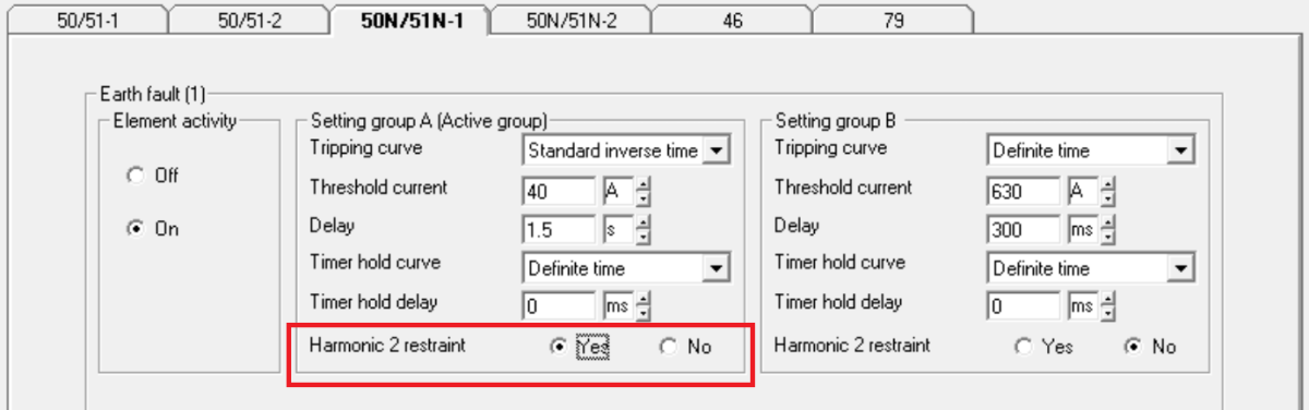
Harmonic Restraint
The harmonic restraint function prevents the relay from tripping when transformers are energized. At the energization of the transformers a large magnitude of magnetizing inrush current flows, which contains a significant second harmonic content. The relay can mistakenly take this zero sequence current from harmonics as a fault current and trip on earth fault, if harmonic restraint is not enabled, however when enabled, the relay can correctly recognize this second harmonic current as an energization event and restrain the relay from tripping. The harmonic restraint function should be ’enabled’ whenever the relay is used for transformer protection.
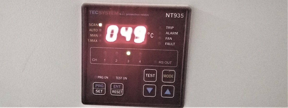
Relay Configuration for 49 - Thermal Overload Function
The 49 - thermal overload function is utilized as a temperature trip for the transformer. A resistor temperature detector or thermistor may be inserted in each of the three phase winding coils of the transformer (dry type transformers are usually manufactured with temperature trips) and the output of those thermistors may be monitored by an external temperature control unit or may be dropped at the digital inputs of the relays. Digital I/Os can then be configured to give a logical trip command to the relay. Most modern numerical relays have multiple digital inputs and outputs to implement logic functions. Typical temperature control units will operate the cooling fans at a fixed set-point and then trip the relay if winding temperature rises further. The set-point is usually programmed during commissioning.
Event Recorder
Event recorders record the fault events as they occur, they should also be enabled for all protection functions.
Cold Load Pickup (CLPU)
Reconnection of a feeder after a prolonged outage causes transient current that remains above the normal FLA value for seconds or even minutes. In this case, if the original pick-up value is increased, protection will be less sensitive. Modern microprocessor relays use different setting groups and programmable logic to implement the cold load pickup function and prevent misoperation during these conditions.
References
This article is accurate and true to the best of the author’s knowledge. Content is for informational or entertainment purposes only and does not substitute for personal counsel or professional advice in business, financial, legal, or technical matters. © 2020 StormsHalted