Our focus is on the British 625-line monochrome analogue system and the waveform specification is given in detail.
What Is Television?
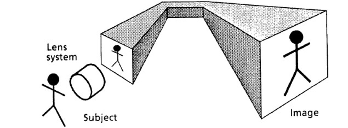
The British Standards Institution has defined television as the “art of instantaneously producing, at a distance, a transient visible image of an actual or recorded scene by means of an electrical system of communication, with or without its accompanying sound”. This article will describe the essential principles of a monochrome analogue CRT television system. In a monochrome system, the brightness of each point of the scene to be televised is converted to an electrical signal. The signal is conveyed to a display where it is converted back into light. The elements of a simple television camera are:
an object to be televised a microphone to capture the sound a camera to capture the image a processor to convert the sound and image into a signal a transmitter to send the signal an aerial to receive the signal a television and receiver to convert the signal and display it
A First Look at Television
The television picture is a two-dimensional image of a scene viewed by the camera. The brightness of each part of a picture can range from black to continuously variable shades of grey to white. To send all the information which describes the whole picture in one go, meaning simultaneously, would be technically difficult, but luckily this is not necessary. In making films, we take a series of still shots and show them rapidly one after the other to create the illusion of movement. This means that the position of objects in the scene has been sampled in the time domain. Integration of the projected pictures by the eye and brain gives a temporal low-pass filter to recover the original moving image. In television, we use sampling even further. The picture that we take at regular intervals cannot be sent instantly. It has to be sent one piece after another by scanning the picture in a regular pattern and this time division multiplies the samples of scene brightness taken from all the elements of the picture. We are used to this scanning process from reading a book! Our eyes have learned to scan the text from left to right, flip rapidly back and also move down to read the next line. The text words are assembled into a serial form for transmission from the page via the eye to the brain. Using an identical scanning process, the information can be written back to give a copy of the original page. Now we must take a deeper look at the sampling operations which are going on, both in the time domain and in the horizontal and vertical dimensions of the scene.
Picture Sampling Rate
All the brightness information in each picture is scanned in one picture period. The number of pictures per second is called the picture frequency. The choice of picture frequency is vital to the design of a television system. The whole scanning process speeds up if the picture frequency is increased. Now if the sampling rate of the picture brightness levels is increased, so that brightness changes in the camera signal occur more rapidly, then a wider signal bandwidth is needed. To save using bandwidth unnecessarily, the picture frequency must be kept as low as possible. A film projector shows a series of still pictures (called frames) in quick succession, which the eye integrates into a moving scene. A rate of, say, 20 to 25 pictures/second gives satisfactory movement portrayal. Cinema film uses 25 frames/second. Compare this with the old silent movies at 15 frames/second, where the picture rate is not quite enough to give smooth movement. Having solved movement portrayal, another problem creeps in. The rapid change from one projected film frame to the next must be concealed. A rotating shutter cuts off the projector light momentarily during the fill pull-down. This causes a brightness flicker that is very noticeable if it occurs below about 40Hz. Unfortunately, doubling the picture (frame) rate to avoid flicker would use twice as much of the expensive film stock. It would also reduce the exposure time for each frame in the camera, making it less sensitive under low lighting conditions. A neat solution is to shutter the light in the projector twice per film frame to give a projected flicker frequency double that of the picture rate, effectively showing each frame twice. In television, the display screen is being continuously over-written from top to bottom of the screen. The old brightness values must decay before the new ones are written in, to avoid a smeared display on moving areas. The decay and rewriting makes the picture flicker and we must design the scanning action to minimise this defect.
Scanning the Picture
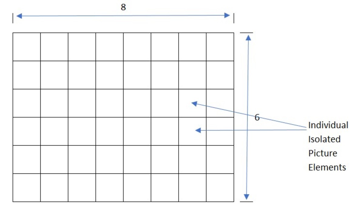
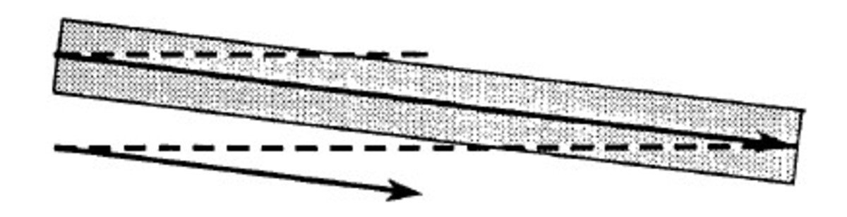
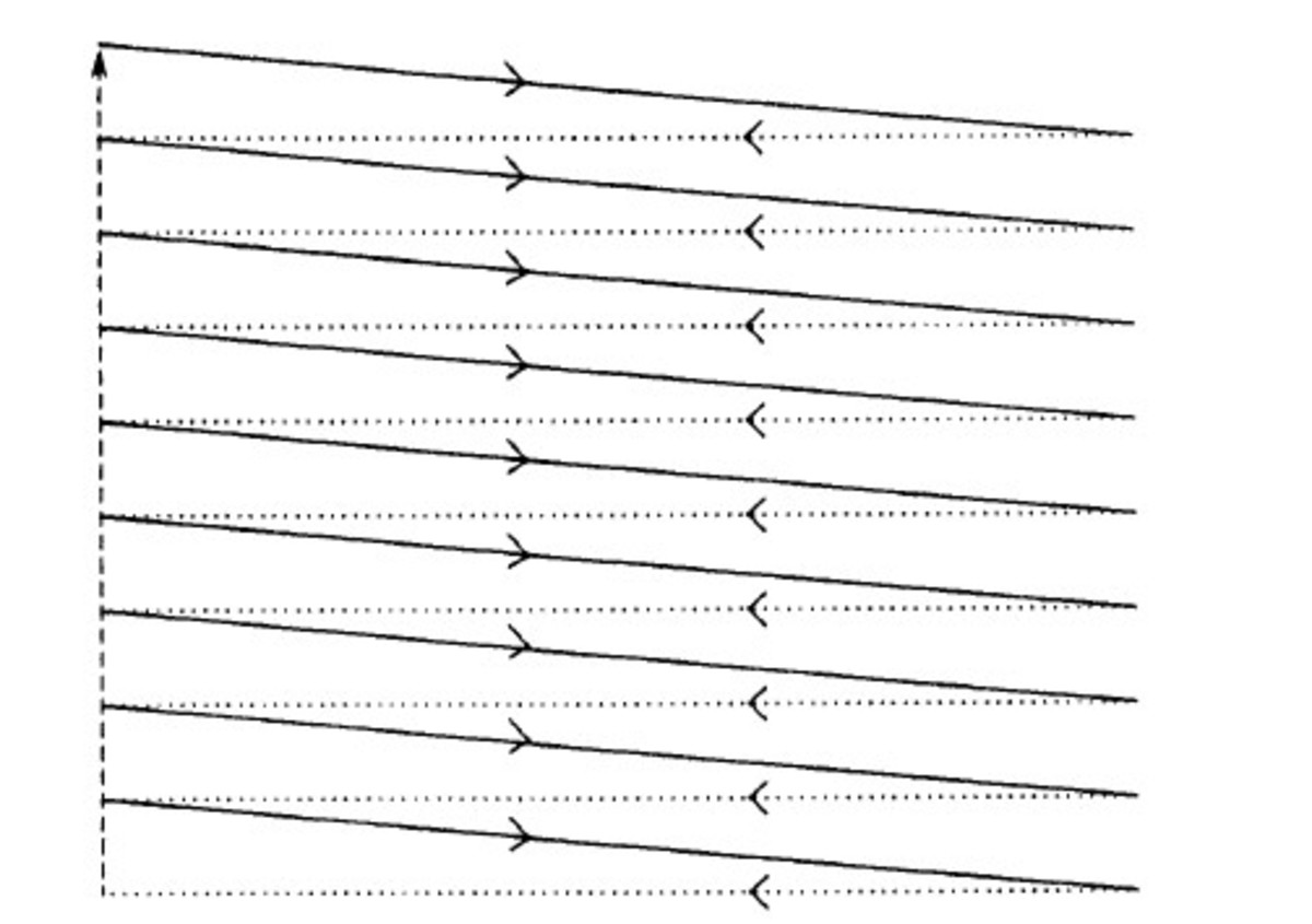
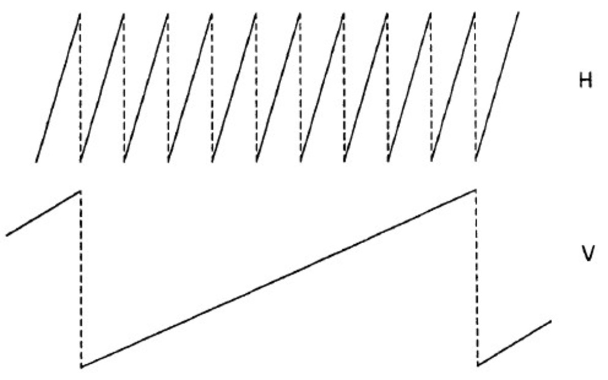
We could imagine the picture divide into a regular patter of picture elements. A simple 48-element pattern is shown below. The scanning process must sample the brightness value (called luminance) of each element in turn. The stream of brightness values will be fed to the correct elements of the display by a similar scanning action. In practice, over 300,000 elements are needed to provide a satisfactory television picture. You can now see why simultaneous transmission of the signal from each element in the camera to the display is not a practical solution. A camera pick-up tube contains a photosensitive surface onto which is focused an image of the scene. Light input from the scene alters the electrical charge inside this layer in a way which is proportional to the amount of light falling on each part of the surface. By scanning the photosensitive surface with an electron beam, a single electrical signal can be generated. Its level at any instant represents the brightness of the light falling on the element currently being scanned. Two separate scanning actions, a fast horizontal motion and a slower vertical motion, occur simultaneously to cause deflection of the camera electron beam. The beam travels from left to right sampling the elements along a line of the mosaic. At the end of the line, the beam is suppressed and then rapidly flies back to the left-hand side. This is horizontal flyback. The slower vertical scan has been pulling the beam downwards all this time, so that when the beam is turned on for the next horizontal scan, it covers the elements on the next line down. At the bottom of the scene, vertical flyback causes the beam to return to the top to start the process again. The line frequency is the picture frequency times the number of lines per picture. The pattern traced by the path of the beam is called a raster. The simultaneous action of the rapid horizontal and the slower vertical scan means that the path of the beam is not quite horizontal, but slopes downwards very slightly across each line. Flyback is drawn as a dotted line and shown as instantaneous, though a practical scanning system will need some time to accomplish flyback. Simplified deflection waveforms for the creation of a nine-line raster are shown below:
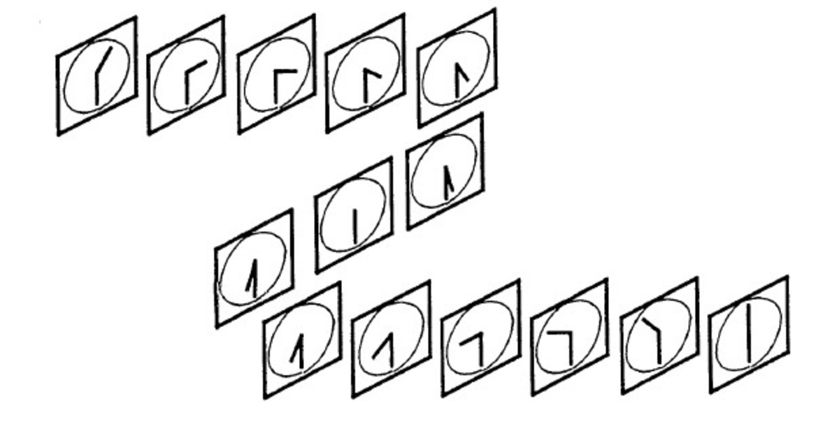
Interlace Scanning
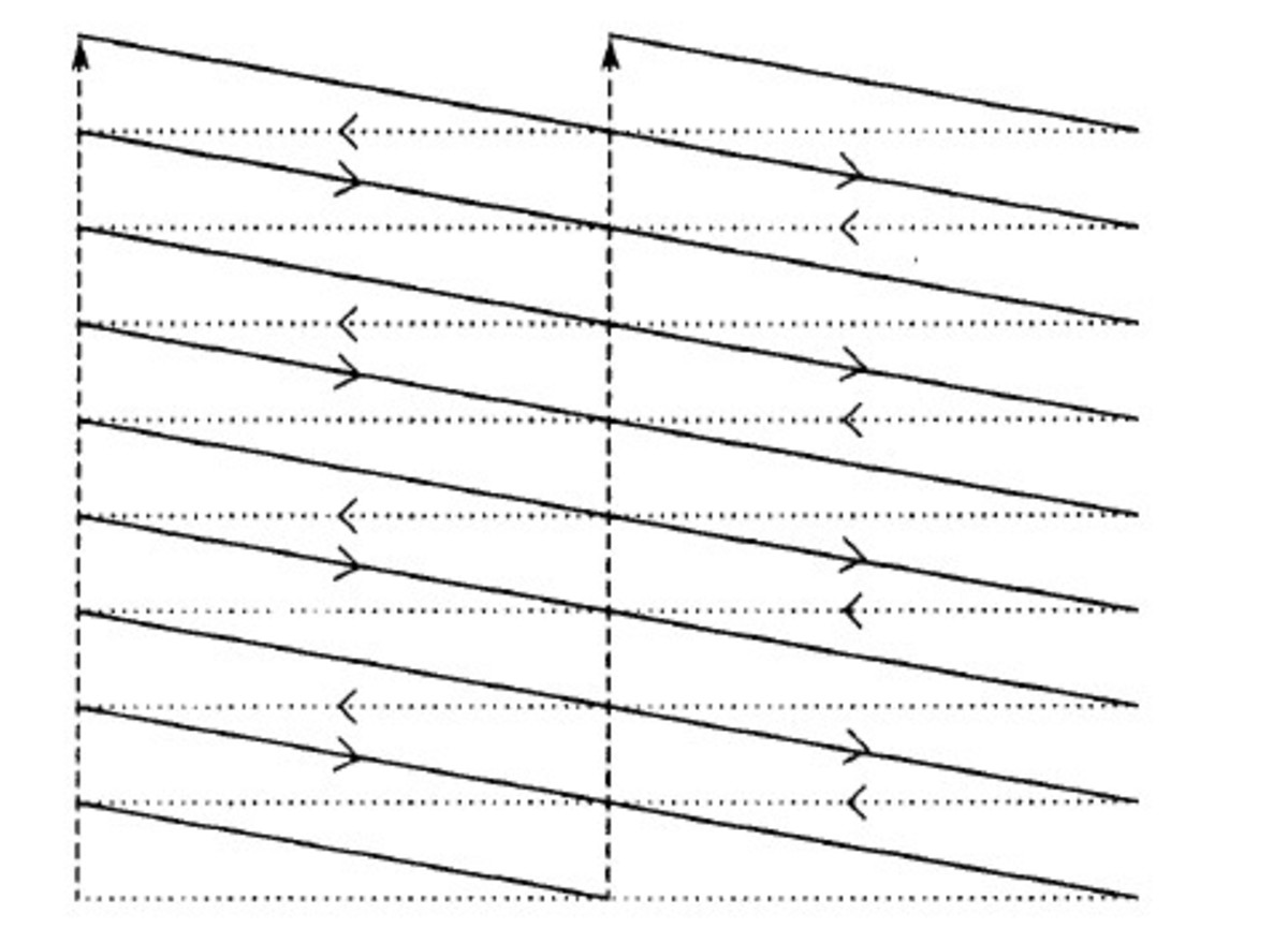
Using interlace scanning, a picture rate just sufficient for good movement portrayal can be used without excessive flicker being seen. Interlace scanning means that the vertical scan rate is doubled, and so downward deflection of the beam causes it to scan every alternate line of picture elements in the mosaic. The beam reaches the bottom of the mosaic in half the picture period and flies back to the top. On the second pass, it scans every alternate line and transmits thosse line left out during the first scan. Two vertical scans, call fields, must be made to sample all the picture elements in the scene. The vertical scan is identical in size and duration on both fields to keep it simple. Interlace will then occur naturally when an odd number of lines per picture us chosen, so that one field ends on a half line, and the other ends on a full line. Relative to the horizontal scan, the vertical retrace starts half a line later on one field. From a position halfway between lines of the last field, the beam flies back to begin drawing lines of the next field in the spaces between. The image below shows a 9-line interlaced raster. For clarity, this is drawn with instant horizontal and vertical flyback. Vertical flyback starts on one field at the end of the horizontal flyback and on the other halfway through a line. Both flybacks are 9 display lines in amplitude. The overall picture frequency remains similar to film, but the flicker occurs at field frequency, twice the picture rate. The non-interlaced display needs double the line frequency, because, to avoid flicker, all the lines have to be scanned in the time of one field of an interlaced display.
Picture and Field Frequencies
Picture frequency is chosen so that the field frequency is very close to the main power frequency. This minimises the visibility of any power line hum picked up on the brightness signal, which was important in the days of AC heated valve technology.
Aspect Ratio
The ratio of width to height of the displayed picture is called the aspect ratio. When television was developed in the 1930s, the film industry was using a 4:3 aspect ratio, and this was adopted for TV. Later developments showed that other aspect rations gave artistic advantages, which is why modern television uses the 16:9 aspect ratio.
Generating the Television Waveform
The television waveform must contain an electrical representation of the brightness of the picture elements along each line of the picture. This is called the Picture Signal component. Scanning is generated in the camera and the receiver by similar circuitry, and there is no need to transit the deflection waveforms themselves in order to match the scanning actions at each end of the system. All we need is sufficient extra information to enable the camera and display scanning to occur together. This is called the Synchronising Signal component. They are added together to give the final video signal for transmission to the viewer. This content is accurate and true to the best of the author’s knowledge and is not meant to substitute for formal and individualized advice from a qualified professional. © 2022 Mr Singh