Copyrights © Ali Khan (Author) Here we will explore:
How RMUs are constructed and how they work. Their utilization in distribution feeder schemes. Lastly, we will see if they are really viable alternatives to conventional switch-gears which their manufacturers promise.
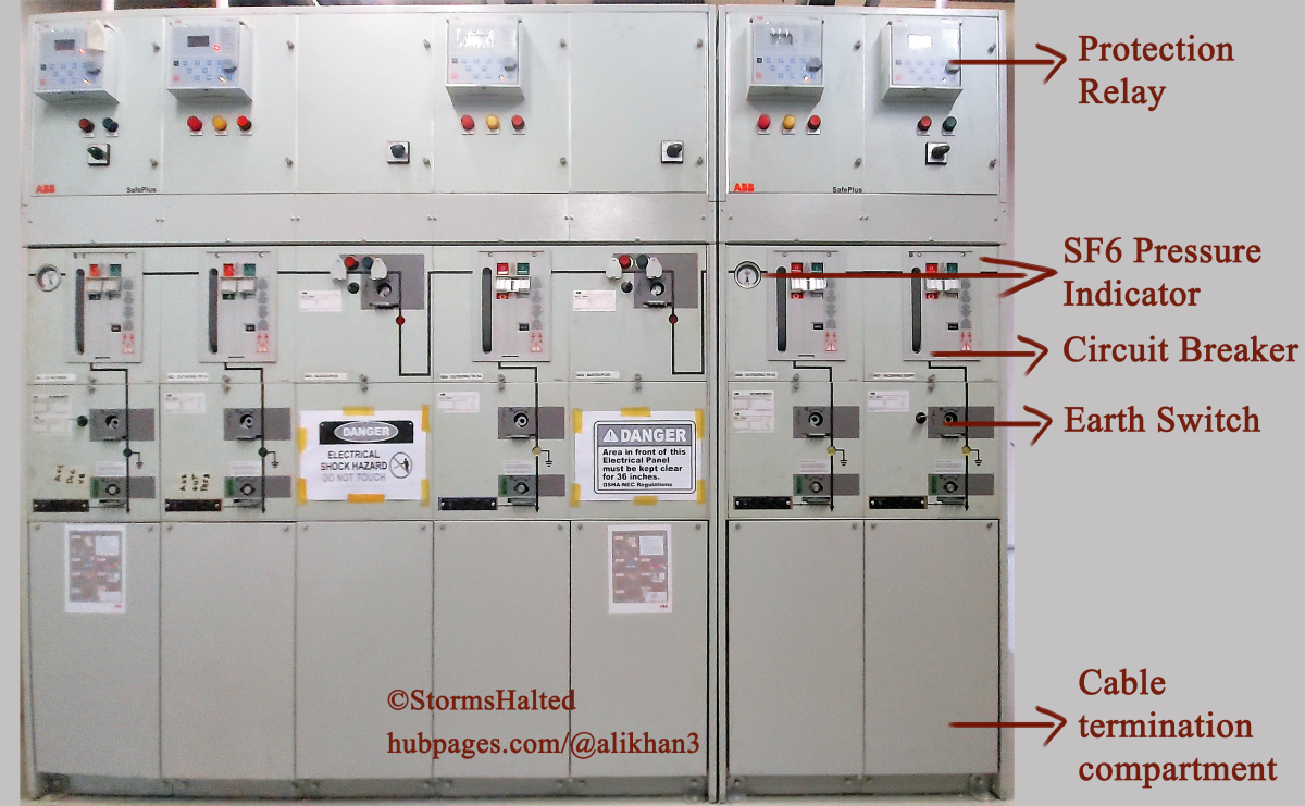
Construction of a Ring Main Unit
A typical ring main unit is essentially an encapsulated medium voltage (11kV - 66kV) bus bar, that has provision to either terminate any number of incoming feeders or rise outgoing load feeders, each in a separate modular compartment.
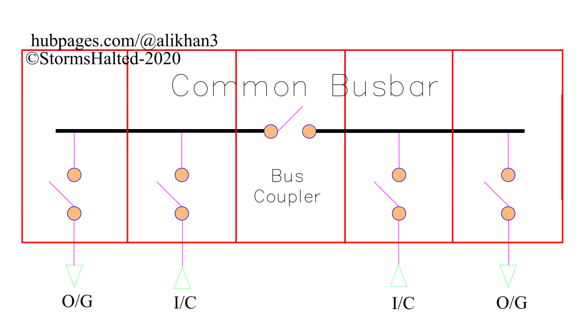
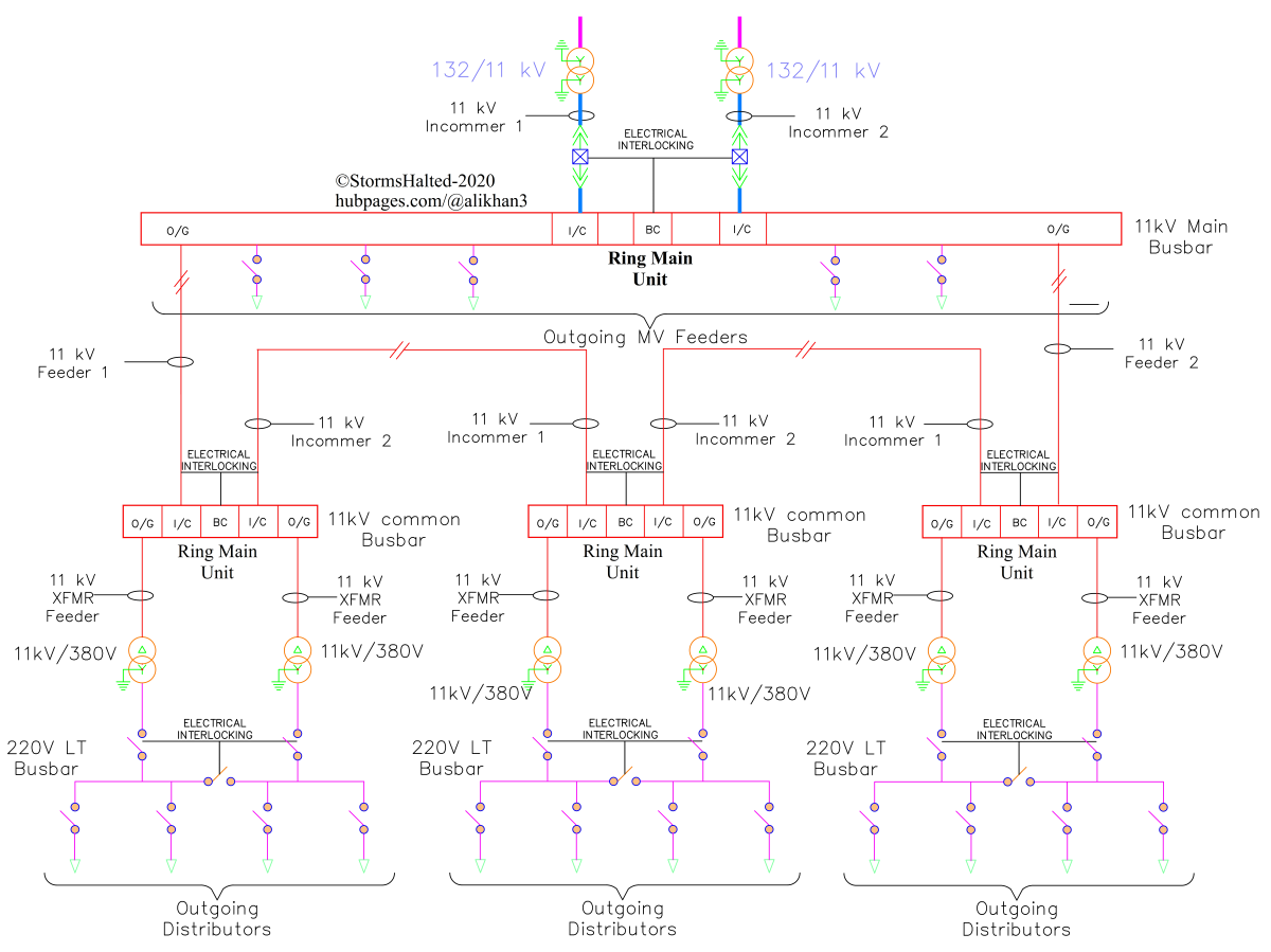
Schematic Diagram of a Typical Ring Main Unit
A typical 5 section RMU can have the schematic as shown in the picture below: This scheme is used to operate two different AC sources in a tie bus bar scheme. (from left to right)
Section 1: Outgoing to 11kV/380V transformer, with protection relay, circuit breaker and metering (all three options). Section 2: Incoming from either 132kV/11kV transformer or another 11kV feeder, with isolator only. Section 3: Bus Coupler, with isolator only. Section 4: Incoming from either 132kV/11kV transformer or another 11kV feeder, with isolator only. Section 5: Outgoing to 11kV/380V transformer, with protection relay, circuit breaker and metering (all three options).
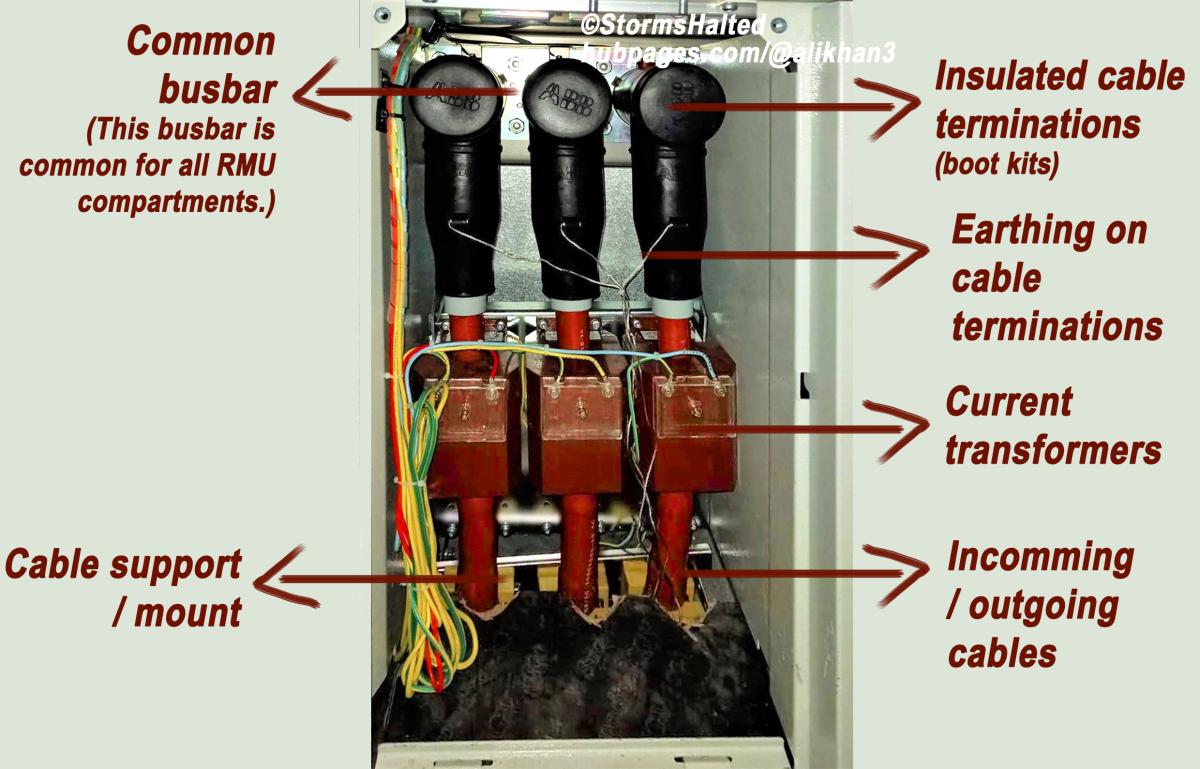
The Common Busbar
Throughout the length of the RMU structure, runs a common copper bus bar, concealed behind the SF6 compartments and covers. Each cable termination terminates on this common bus bar.
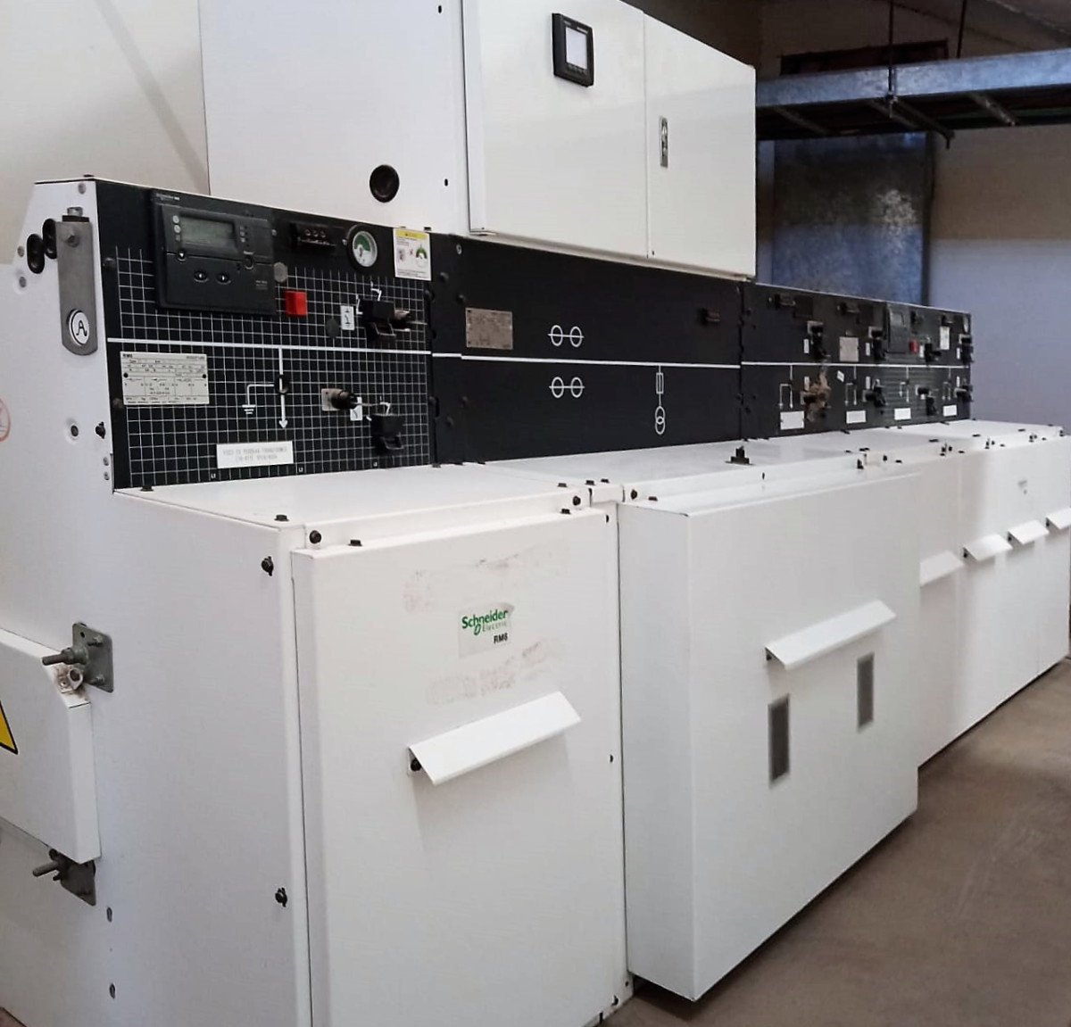
Modular Compartmentalized Design
RMUs are ordered according to the number of sections that are required for e.g., engineers may order either a 3 - section, 5 - section, 7 - section or even higher sections unit, depending on their distribution scheme. Schneider Electric Industries SAS. Adapted from RM6 Official Catalouge Each section/modular compartment may either have, depending on the requirement: RMUs are extendable; it is possible to join an existing installation with additional sections for expansion. Copyrights © Ali Khan (Author)
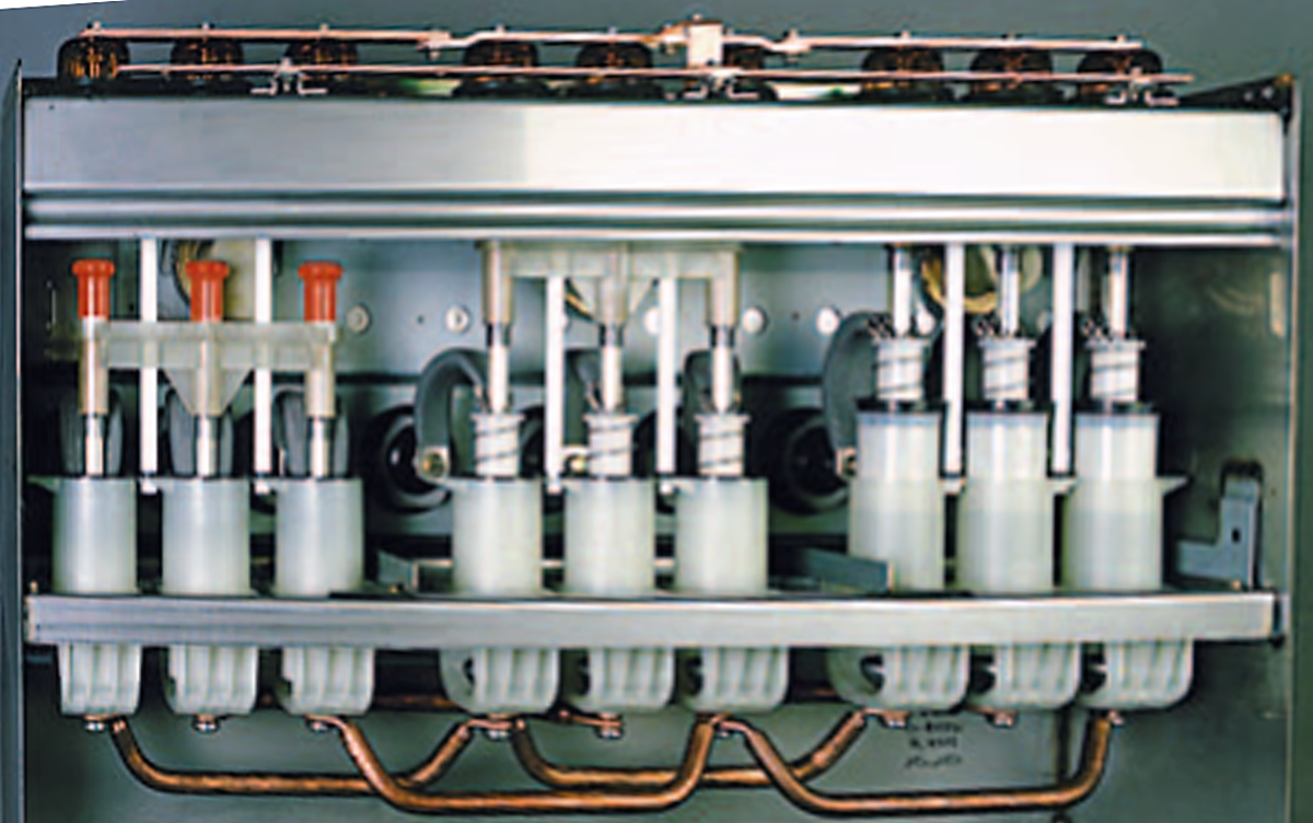
Sealed Cable Terminations
MV cables are terminated onto the common bus bar in separate compartments. Each cable termination joint is completely enclosed in a special insulating plastic cladding (bootkits) that eliminates the possibility of flash-over with the nearest conductor. After the cables are bolted onto the common bus bar, a vacuum pump is used to seal the plastic cladding on the cable termination bolts.
What Makes an RMU Smaller in Size?
The fact that an RMU occupies 40% less space compared to traditional vacuum circuit breaker trolleys is enabled by: Copyrights © Ali Khan (Author)
Sealed termination boot kits:
They completely encapsulate the termination points of MV cables and preventing the possibility of arc flash-over even if the cables are spaced closely. In other words, they significantly reduce the spacing requirement between cables and enable them to terminated more closely to each other.
Hermetically Sealed SF6 Tanks:
They are usually smaller in size as compared to traditional vacuum circuit breakers, due to superior arc quenching properties of inert Sulphur Hexaflouride (SF6) gas.
Distribution Philosophy of Ring Main Units
RMUs are commonly employed in ring main distribution schemes, where their compact size and modular installation have made them quickly replace switch-gears. A standard ring main feeder with RMUs is illustrated below: In this scheme, a typical downstream substation has: Copyrights © Ali Khan (Author)
An RMU, having an incoming and outgoing feeder Two transformers LT tie-bus bar
RMU vs. Conventional Switch-Gear, Which One Is a Better Choice?
Should you opt for the RMU or go with the traditional Vacuum Circuit Breaker trolley switch-gear in a new installation? This is the question operational engineers, facility designers and consultants face when they are designing new electric installations or overhauling existing installations. When faced with this question, engineers can evaluate their choice on the basis of the below factors and make an informed decision based on their particular needs.
Conclusion
Space constraints and installation costs will make RMU the preferred choice over switch-gears. Operational life cycle and switching requirements will make switch-gear the preferred choice. Costs and logistic intervals vary according to location but should be considered in the decision-making process.
This article is accurate and true to the best of the author’s knowledge. Content is for informational or entertainment purposes only and does not substitute for personal counsel or professional advice in business, financial, legal, or technical matters. Copyrights © Ali Khan (Author) © 2020 StormsHalted